Linear Pendulum Assembly
I made this in a weekend.
My interview for Heirloom required a presentation on a project that I was passionate about. Realizing that it had been a long time since I worked on my college projects (and I didn’t really find them interesting), I decided to put this together the weekend before my presentation. It ultimately got me the job.
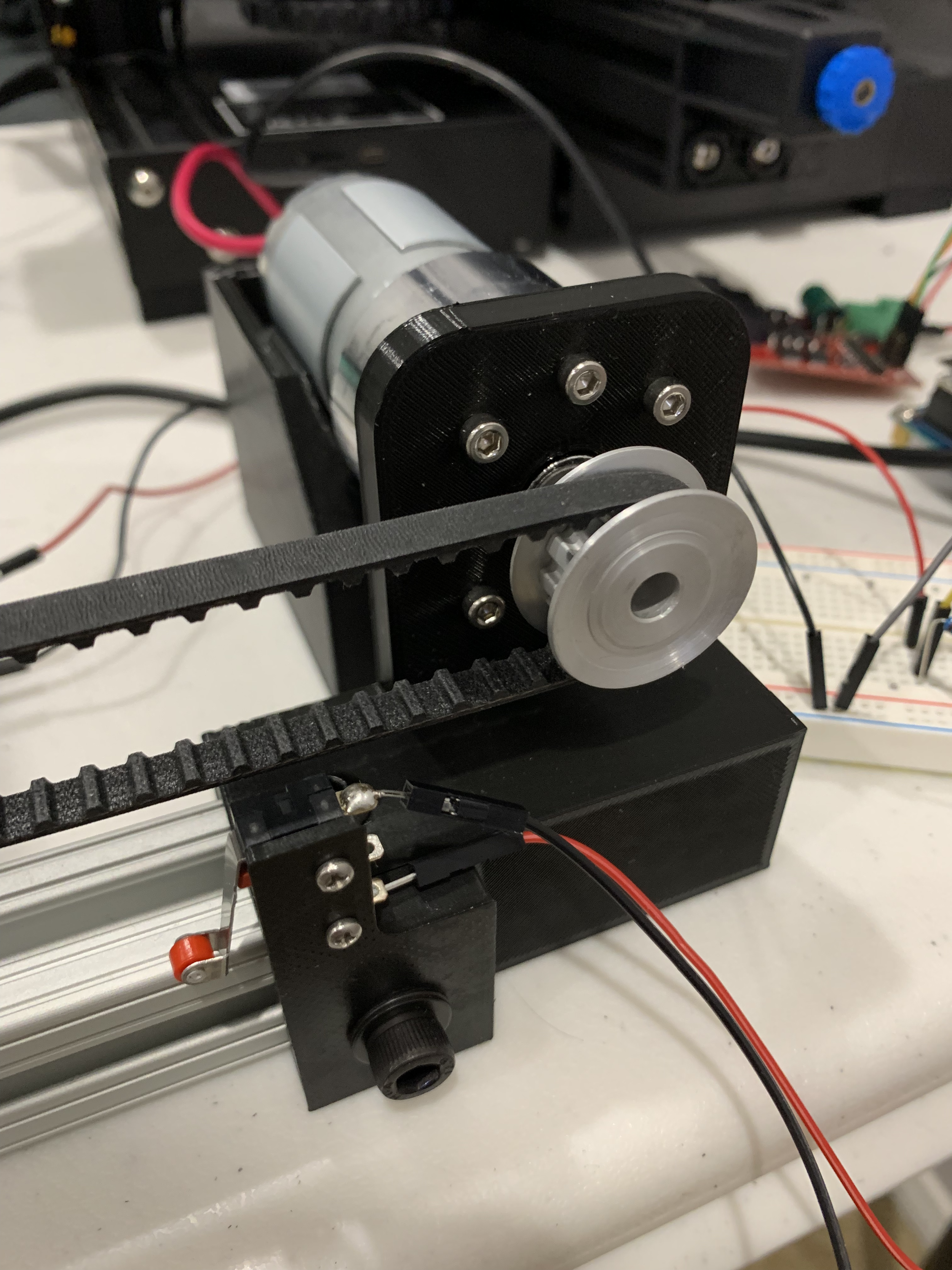
Mechanical design was all done in Fusion 360. I obtained the extrusion and hardware on McMaster and electronics from Digikey and Amazon. The black plastic parts seen in the images were 3D printed.
Motor control was done using an ESP32 microcontroller via the Arduino IDE. I used this DC gear motor that, in hindsight, was a pretty lousy choice for this application. The motor driver I sourced from Amazon was also particularly bad, containing blatant errors in its documentation that took several hours to debug and identify.
Closed-loop control was achieved using a rotary encoder attached to the belt on the side opposite to the motor, in addition to two simple limit switches on either end of travel.
This project taught me a lot of what not to do when designing a belt-driven linear motion system, e.g. using load-bearing 3D printed parts, adding almost no adjustability for things like motor mounting, sizing a motor based entirely on “intuition,” and using a non-standard (i.e. not an Arduino) microcontroller because my older brother who is a computer engineer at Rivian said it would be cool.
This video shows the carriage homing sequence on start-up. Limit switches on either end of the assembly defined the limits of travel, while a rotary encoder was used to determine the number of pulses in a full sweep. From the number of pulses, the middle point was calculated and the carriage moved to that position.